Explain how to map the statechart to the state design pattern.
State Design Pattern
The State Design Pattern is used in system design to allow an object to alter its behavior when its internal state changes,
effectively making the object appear to change its class.
🔄 Core Intent:
Allow an object to change its behavior when its state changes.”
✅ Use Case in System Design: a system must behave differently based on its current state, and state-specific behavior is scattered across many conditional statements (`if`, `switch`), the State pattern offers a clean solution.
🧱 Key Components:
Context: The class that contains a reference to a State object and delegates state-specific behavior to it.
State Interface: Declares the behavior that changes depending on the state.
⚙️ How It's Used – Example:
Suppose you're building a "media player" with states: `Playing`, `Paused`, and `Stopped`.
// State interface
interface PlayerState {
    void pressPlay(MediaPlayer context);
}

// Concrete States
class PlayingState implements PlayerState {
    public void pressPlay(MediaPlayer context) {
        System.out.println("Pausing playback...");
        context.setState(new PausedState());
    }
}

class PausedState implements PlayerState {
    public void pressPlay(MediaPlayer context) {
        System.out.println("Resuming playback...");
        context.setState(new PlayingState());
    }
}

// Context
class MediaPlayer {
    private PlayerState state;

    public MediaPlayer() {
        state = new StoppedState();
    }

    public void setState(PlayerState state) {
        this.state = state;
    }

    public void pressPlay() {
        state.pressPlay(this);
    }
}
🎯 Why Use It in System Design?
Eliminates large conditionals for state transitions.
Makes state transitions explicit and encapsulated.
Improves scalability: new states can be added without modifying existing logic.
Encourages Single Responsibility Principle each state handles its own logic.
🧠 Real-World Analogies:
TCP Connection: Can be in states like Established, Listening, or Closed.
Workflow Engines: Each document or request goes through states like Draft, Submitted, Approved, Rejected.
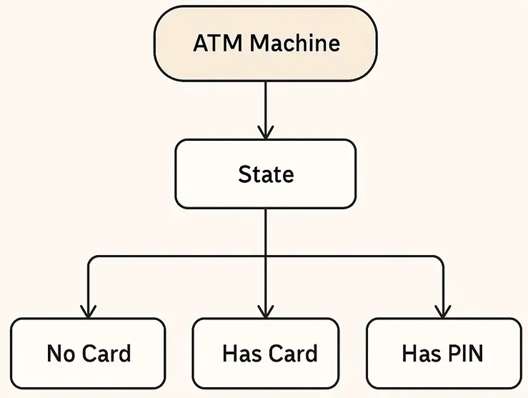
🏦 Diagram Overview – ATM State Design Pattern
The diagram is a hierarchical flowchart representing how an ATM Machine uses the State Design Pattern to manage its behavior based on different internal states.
📦 Components in the Diagram:
ATM Machine (Context) –
At the top of the diagram is a rounded rectangle labeled ATM Machine.
This represents the Context class. It holds a reference to the current state object and delegates operations to it.
State (Interface or Abstract Class) –
Below the ATM Machine is a box labeled State.
This defines the common interface for all concrete states. It declares methods like insertCard(), enterPin(), withdrawCash(), etc.
Concrete States
Branching out from the State box are three child nodes:
No Card
Has Card
Has PIN
Each of these represents a concrete implementation of the State interface:
No Card: The ATM is idle and waiting for a card.
Has Card: A card is inserted, waiting for PIN.
Has PIN: A correct PIN is entered; user can perform operations like withdrawal.
🔁 Behavior Control:
The arrows between boxes suggest that:
The ATM Machine delegates actions to the current state object.
As the user interacts (e.g., inserts a card, enters a PIN), the ATM transitions between states, altering its behavior dynamically.
✅ Benefits Illustrated:
Encapsulation of state-specific logic.
Elimination of complex if/case logic.
Open/Closed Principle: new states can be added without modifying existing logic.
Managing state-specific behavior
When an object exhibits a lot of state-specific behavior the code can become large, complex, and difficult to follow.
For each behavior that the object can manifest, the implementation may be
different for each state of the object. For example, a relatively simple object with six states and six behaviors would require 36
blocks of implementation code, one block of code for each behavior for each state.
View the image below to see an example of this.
Here's the extracted pseudocode from the image:
CASE <if state = state #1>
    CASE <if behavior #1>
        Implementation for behavior #1
         <if behavior #2>
        Implementation for behavior #2
         <if behavior #3>
        Implementation for behavior #2
         <if behavior #4>
        Implementation for behavior #2
         <if behavior #5>
        Implementation for behavior #2
         <if behavior #6>
        Implementation for behavior #2

CASE <if state = state #2>
    CASE <if behavior #1>
        Implementation for behavior #1
         <if behavior #2>
        Implementation for behavior #2
         <if behavior #3>
        Implementation for behavior #2
         <if behavior #4>
        Implementation for behavior #2
         <if behavior #5>
        Implementation for behavior #2
         <if behavior #6>
        Implementation for behavior #2

>>> continue for each state possible for the object <<<
This nested structure is a classic code smell for when the State Design Pattern is needed,
if you see deep `CASE` or `IF` logic based on both state and behavior, refactor using polymorphism and encapsulated state objects.
State Design Pattern
State Pattern
One technique for coping with the complexity of state-specific behavior is the state design pattern. This pattern uses the concept of delegation to separate the implementation of a behavior from the object that is responsible for the behavior.
For example, most of us are responsible for filing taxes. However, for some of us, the process is extremely complex and requires assistance from an expert. We retain ultimate responsibility for filing the taxes, but we delegate the actual process to a
specialist who does it for us. When the tax specialist is finished, he/she returns the results to us.
View the diagram below to see the key components of the state design pattern.
State Design Pattern
When an object's behaviors differ depending on the object's state, you can define new objects that represent the
object's state. Each unique state object type has its own implementation for each behavior. When the object needs a behavior it "delegates" the behavior to the appropriate state object. Once the behavior has been completed, the state object returns control to the original object. Let us look at a Java example:
Note how the operation simply invokes another operation of the same name on the object referred to by the state attribute. The interface does not really even have an implementation of its own.
Map the state diagram to the state pattern
The statechart diagram provides an explicit description of the states of an object.
To create the state pattern in your class diagram view the series of images below and follow the steps.
The state pattern is not appropriate for every application of state-specific behavior. However, when you are faced with increasing numbers of states and a variety of behaviors, the pattern can pay huge dividends in ease of maintenance and understandability.
State Design Pattern Description
1) Create an attribute in the base class called 'status' or 'state' or something similar to convey its purpose.
2) For each state in the statechart diagram, create a corresponding class definition.
3) Draw a generalization relationship from each state object to a single superclass.
4) The data type of the state/status attribute of the base class should refer to the new superclass (this will allow the base class to refer to any of the state subclasses through this attribute). The aggregation symbol is commonly used to indicate that the state generalization is a
'part of' the make-up of the base class.
5) For each event in the state transition diagram: a) Add a corresponding interface to the base object. b) Add a corresponding (identical) interface to the state superclass (this will cause every state subclass to inherit the interfaces).
6) To implement the base object interfaces, invoke the corresponding interface on the attribute that holds the state subclass reference.